To begin this project, I
wanted to have wireless joysticks to enjoy Mame, Daphne, Stella,
VPinball, etc. No one makes such a beast that I could find,
so I decided to build my own by modifying a bluetooth keypad and
building a couple small control panels.
To start, you need to map the keyboard and make sure that your
key-combinations will work without ghosting/masking. I used a
program called keyscan.exe (Windows only). The nice thing
about this program is it shows the number of keypresses visually and
tells you how many button presses are being recognized. This
makes it pretty easy to map out the keypad and determine the best keys
for the job. For the
keyboard I used, the layout is as follows (to support 2 players, with 3
buttons each)
Targus Bluetooth keypad:
| V+ |
Rocker w/ Play
Stop, FF, Rew |
Media |
| V- |
BK FF |
| Mute |
|
| NL |
/ |
* |
BS |
| 7 |
8 |
9 |
- |
| 4 |
5 |
6 |
+ |
| 1 |
2 |
3 |
Ent |
| 0 |
00 |
. |
Some of the keys above aren't mappable, and others are hotkeys that
Windows understands but don't show up as normal keypresses.
However, with a little time and keyscan.exe, it is easy
enough to
figure out how to make this work for 2 players.
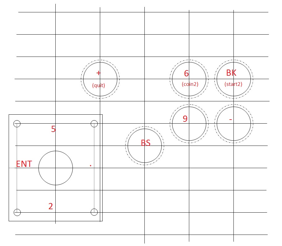
Player 1 (no masking, can concurrently hit each diagonal and all three
buttons)
| Joystick 1 |
B1 |
B2 |
B3 |
|
7 |
|
|
|
|
| / |
|
* |
4 |
1 |
0 |
|
8 |
|
|
|
|
Player 2 (no masking, can concurrently hit each diagonal and all three
buttons)
| Joystick 2 |
B1 |
B2 |
B3 |
|
5 |
|
|
|
|
| ENT |
|
. |
BS |
9 |
- |
|
2 |
|
|
|
|
Common Buttons (keys mask with each other or with the player 1/2
controls)
| Coin1 |
Coin2 |
Start1 |
Start2 |
Quit |
| 3 |
6 |
FF |
BK |
+ |
To begin....
I started with a piece of pine I purchased from
Lowe's. The pine is a lighter than MDF and will build a nice
light-weight control panel. I purchased "Craft Master's Pine"
in
a 3/4" x 24" x 48" sheet.
The cuts are as follows:
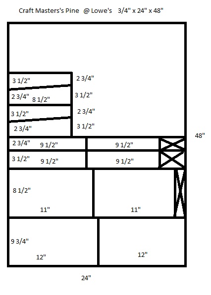
The top of the control panel is 9 3/4"x12" (9" x 12" to the start of
the curve), with a slightly curved front.
The bottom of the control panel is 8 1/2" x 11"
The front of the control panel is 2 3/4" x 9 1/2"
The sides of the control panel are 2 3/4" x 8 1/2" x 3 1/2"
The back of the control panel is 3 1/2" x 9 1/2"
With the button layouts like:
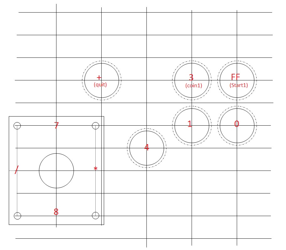 |
 |
| Player
1 |
Player 2 |
Next, holes in the contol panel (use tape to ensure the top doesn't
splinter)
The next section discusses the inner-workings of the numeric keypad,
and how to take it apart and make it MAME-usable.
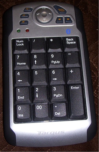
MAME works by using keyboard inputs. As is indicated at the
top of this post, the keymappings for this Targus Bluetooth Numeric
Keypad support up to two joysticks with 3 buttons each (assuming of
course you have two keypads!).
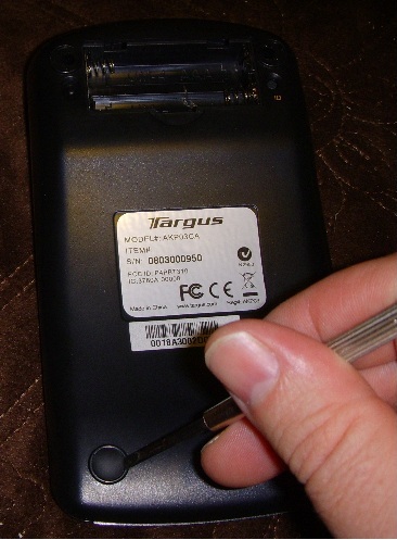
To actually pull this off, we need to take apart the keypad and figure
out how to solder wires for each of the buttons. So, to
begin,
flip the keypad over and remove all four of the rubber feet with a
small flat-head screwdriver.
Once those rubber feet are gone you can remove the 4 screws
and pry the
cover off (slide the screwdriver carefully along the side) giving you
the internals of the keyboard.
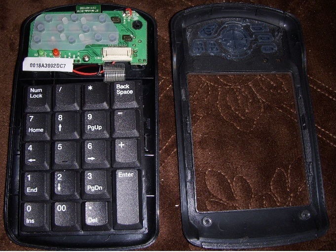
You can remove the keyboard portion by sliding the plastic clip open,
and the rubber button pads on the top just come off. (NOTE:
Not
knowing
what to expect, one of my keypads was sacrificed and I took it
completely apart - underneath the key's are some plastic springs which
compress rubberish pads. These rubberish pads are formed by a
piece of plastic with flexible connectors, folded into two with each
key's connector being formed by both sides of the flexible connector
overlapping. As the button is pushed, the two layers compress
causing an electical connector to occur, signaling the keypress.
You can see what it looks like with the rubberish pads look
like in the picutre below since I tore two of them away.
However, this is NOT something that you solder a wire to
regrettably.)
As it turns out, it was necessary to sacrifice the keypad because we
also have to map which inputs map to which key.
 |
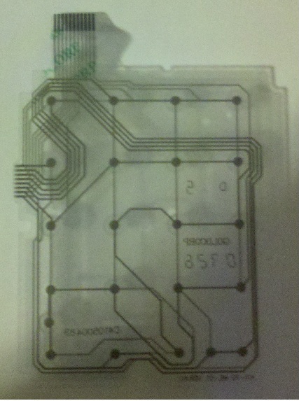 |
| Top
of flexible keypad layer |
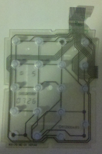
Bottom
of flexible keypad layer |
Once you can see the circuit layout, it is easily possible to determine
which pins are connected when the keys on the keypad are pressed.
The map is as follows (showing the pair of connections
necessary for the 11-pin connection):
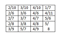
Targus Bluetooth keypad with pin-outs identified:
V+
(5/9) |
Rocker w/ Play
Stop, FF, Rew
(1/8)
(1/10) (1/11)
(1/9) |
Media
(2/9) |
V-
(5/11) |
BK FF
(3/11) 2/11) |
Mute
(5/10) |
|
NL
(2/10) |
/
(3/10) |
*
(4/10) |
BS
(1/7) |
7
(2/6) |
8
(3/6) |
9
(4/6) |
-
(4/11) |
4
(2/7) |
5
(3/7) |
6
(4/7) |
+
(5/6) |
1
(2/8) |
2
(3/8) |
3
(4/8) |
Ent
(5/8) |
0
(3/9) |
00
(5/7) |
.
(4/9) |
So....on to figuring out the pin out connections for the thin flex
cable connection (11-pin) to the circuit board. Using a
multimeter in 'continuity' mode, a small wire to insert into the
flex-connector, and a little patience this is the pin-out diagram for
both sides of the board.
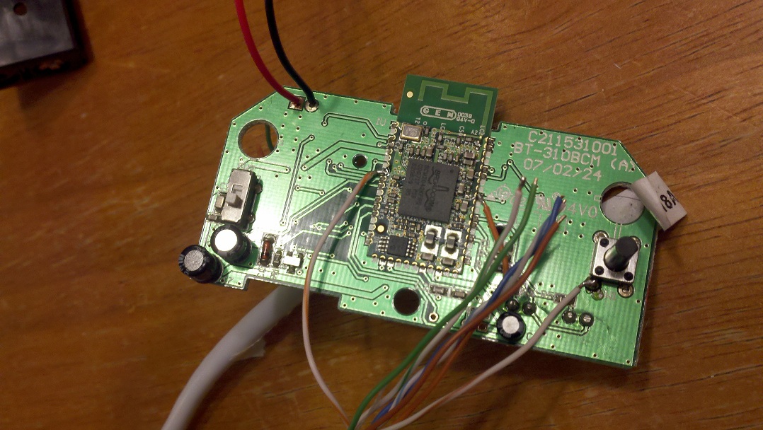
On the top, we have pins 1,2,3,5,8,9,10,11 are all available on the
various pads - should be a good place to solder a wire and easy to get
to. We aren't going to need those multimedia buttons anyhow!
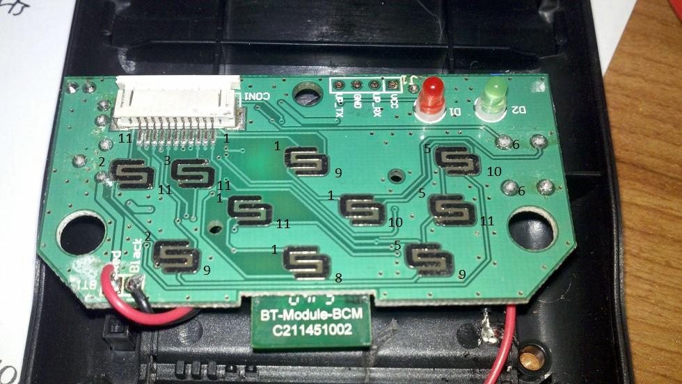
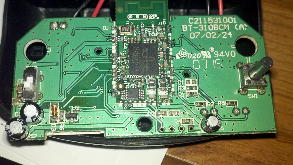
On the bottom, we have pins 4,6,7 - 4,7 will have to be soldered to the
connectors on the daughter card, 6 can actually be soldered to either
the
front or back as that connection is available on the button on the
right. You will have to select the picture below to get the
larger size, otherwise the numbers aren't visible by the daughter card.
The benefit of soldering it all together this way, is you can also use
the keyboard if you need to associate the bluetooth device or something.
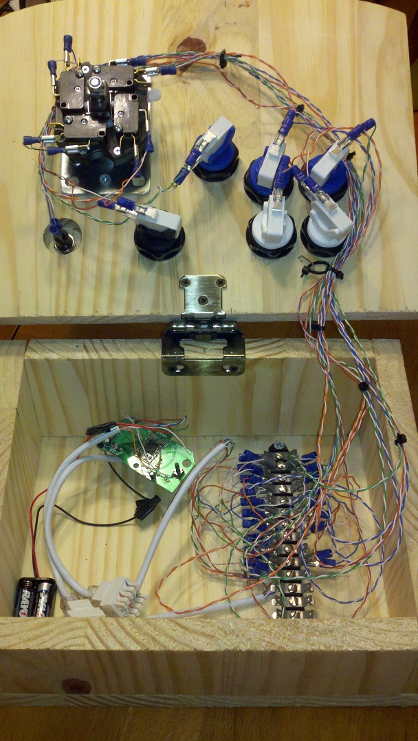
Followed by....putting it all together.
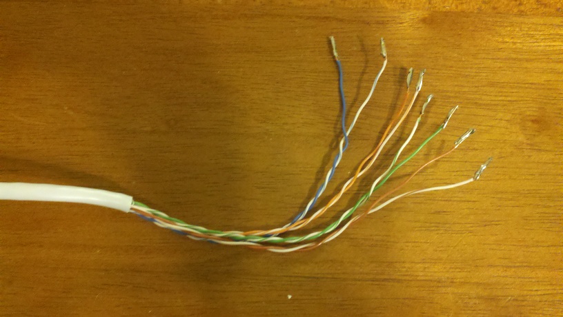
First, I used CAT-5 ethernet cable for the wiring. I stripped off a
large section
of the outside jacket and then bundled the wires in order to make a
neat cabling
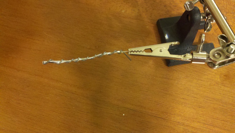
job. To begin, you need to make the connectors for the wires large
enough to get
crimped. I took a piece of wire, folded it over itself, then soldered
it into
one large chunk. This wire was then soldered to the ends of the
ethernet wires and
snipped off to give a end large enough to crimp.
At this point, I installed RJ-45 Cat-5e connectors and RJ-45 Cat-5e
keystones to the ethernet cable
to make it easier to connect/disconnect if required.
The wires need to be carefully soldered to the correct pin location on
the bluetooth daughter card.
Following the pinouts above, you should make the following connections
to the top and bottom of the card.
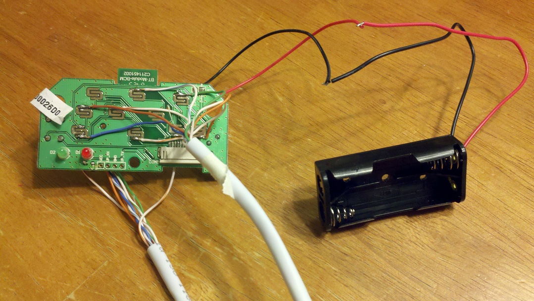
Finally, carefully bundle and tie off the cabling, mount the battery
connector, and make sure
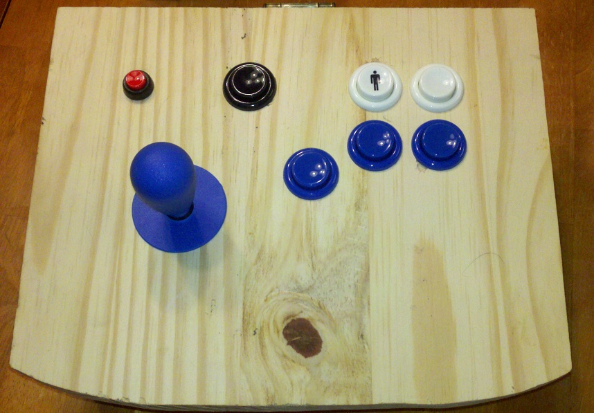
everything has enough room to close/open in the cabinet. Your finished
product should look
as follows
Be careful of the BT device connect button - it is very easy to hit
which will cause your device to
attempt a re-sync with the computer. The keyboard will go to sleep if
not in use, however you can
use the power switch to help save your batteries. The small red button
was linked to the NUM LOCK
key on the keyboard since that is the key to wake up the device.
|